
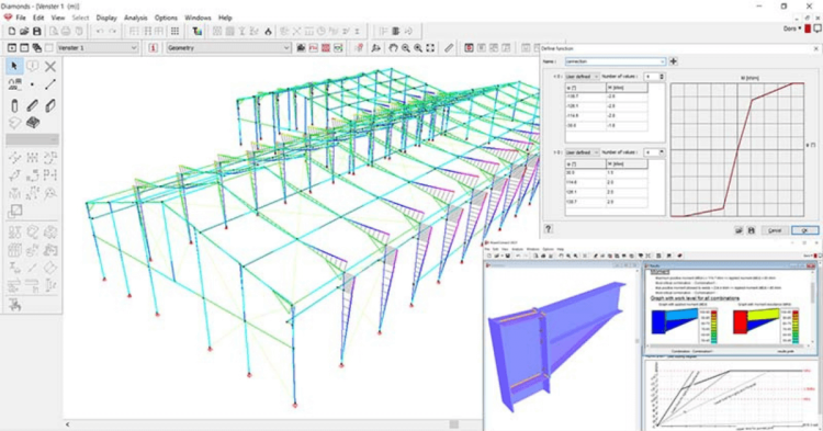
Structural design and analysis is the process engineers use to make sure a building or structure can safely carry every load it will face — from its own weight to wind, snow, and earthquake forces — over its full lifetime. It happens in five stages: modelling, load analysis, structural analysis, structural design, and detailing. Below, we walk through each stage, then work through a simple example to show how they fit together.
The 5 steps of structural design and analysis
1. Modelling
Before any calculation happens, the structure has to be simplified into something a computer (or an engineer, by hand) can actually calculate. Start from the architectural model — what the building looks like in reality — and strip it down to just the load-bearing skeleton: foundations, columns, beams, frames, trusses, walls. This simplified version is called the schematization, the wireframe model, or the mechanical model, and it’s the foundation everything else is built on: get it wrong, and every downstream calculation inherits the error.
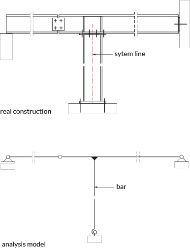
Typical elements in a structural model:
- Beams;
- Columns;
- Struts and ties;
- Slabs;
- Shear walls;
- Membranes.
Modelling also means choosing materials — steel, concrete, timber, or a mix — and assigning first-pass dimensions to each element (width, depth, thickness), usually based on rules of thumb, since these get refined later. Finally, the boundary conditions — how each member connects to what’s around it — need to be defined, since that determines how loads actually flow through the structure.
Read more about modelling in our post about schematizing.
2. Load analysis
Next, identify every load the structure could realistically face over its lifetime:
- Dead loads, meaning the self-weight of the structure
- Live loads: occupancy of people in buildings, moving equipment, and the movement of cars on bridges;
- Wind loads: any horizontal, uplift or shear pressures or forces that the wind exerts on a building;
- Snow loads: only applicable for structures expected to receive snowfall;
- Earthquake loads: when the structure is in a seismic region;
- Earth pressure: to be applied for tunnels, retaining walls, cellars;
- Water and ice: for some structures such as bridges, offshore platforms, and coastal structures;
- Thermal loads: Unequal heating or cooling of parts of the structure create high stresses;
- Dynamic loads: for example, induced by machinery.
In practice, loads don’t act one at a time — they combine. Dead load plus live load is one combination; dead load plus wind is another. Part of load analysis is working out which combination is worst-case for your specific structure, which is exactly the kind of repetitive, error-prone work that structural analysis software (rather than hand calculation) is built to automate.

3. Structural analysis
This is where you calculate how the model behaves under each load combination: the internal forces (shear, bending moment, normal force, torsion), reactions, and deformations produced by each one. For a single beam or column, this is doable by hand. For anything resembling a real 2D or 3D structure, it means solving large systems of equations, which is exactly where hand calculation becomes slow and error-prone. This is what dedicated finite element analysis (FEA) software like BuildSoft’s Diamonds is built for: fast, accurate results without the manual matrix work.
4. Structural design
With the analysis results in hand, structural design is where you size each element to actually meet the requirements (stability, strength, and stiffness) set out in the relevant design code. If the initial (estimated) dimensions from step 1 pass, you’re done, though there’s often room to optimize for a more economical design. If they don’t pass, you go back, adjust the dimensions, and repeat the analysis-and-design loop until every requirement is met.
Design codes vary by country, so knowing the local code your project falls under is part of the job, not an afterthought.
5. Detailing
Once the global analysis and design are finished, detailing covers two things:
- Where connections, splices, and overlaps go : beam-column joints, column base connections, and similar.
- How : the specific reinforcement layout, bolt grade and count, weld throat thickness, end plate sizing, and so on.
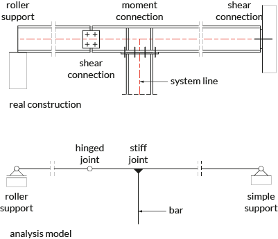
Detailing decisions directly affect ductility. In concrete, a well-balanced reinforcement layout in beams and columns improves a structure’s ability to deform without failing. In steel, planning connections strategically (for example, keeping beam splices near column edges rather than at midspan, where bending moment is close to zero) can cut costs by simplifying the connection to a shear-only joint.
A real life example
How the 5 steps apply to a simple beam example
A steel floor beam spanning between two columns, exposed to wind on one facade, walked through each stage of structural design and analysis.
- Model the beam and its supports
Simplify the beam, its supporting columns, and their connections into a wireframe model, with boundary conditions defined (e.g., pinned or fixed supports). - Identify the loads
Determine dead load (the beam and floor’s own weight), live load (people and furniture on the floor above), and wind load (pressure on the exposed facade) . Next work out the worst-case combination, likely dead + live or dead + wind. - Run the structural analysis
Calculate the bending moment, shear force, and deflection the beam experiences under each load combination. - Check the design
Determine dead load (the beam and floor’s own weight), live load (people and furniture on the floor above), and wind load (pressure on the exposed facade) . Next work out the worst-case combination, likely dead + live or dead + wind. - Detail the connection
Specify the beam-to-column connection such as bolt count, plate size, weld requirements, based on where the design places the connection along the beam.
FAQ
Next step
Want to see how this looks in practice? Try Diamonds free for 30 days — fully functional, no obligation.


