Software for structural analysis of steel, concrete and timber constructions
Diamonds is the perfect software for analysis of steel, concrete and timber structures. Watch some videos, look at the brochure or read more about the advantages of Diamonds. Each Diamonds license can be extended with additional modules such as fire resistance, seismics, moving loads, ….
Materials
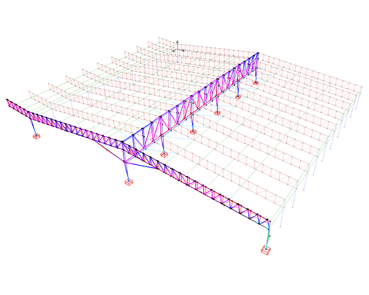
Steel
On executing the Eurocode and AISC steel resistance and buckling verifications, the appropriate cross-section classification is taken into account. Buckling lengths and lateral torsional buckling supports are specified in no time or automatically calculated. Based on these checks Diamonds performs a cross-section optimization. Connections can be transferred to PowerConnect.
- Eurocode 3 (UK, DE, ES, PL, ...) and AISC- LRFD
- Extendable built-in section library
- Cross section classification
- Buckling length calculation
- Lateral torsional buckling supports
- Cross-section optimization
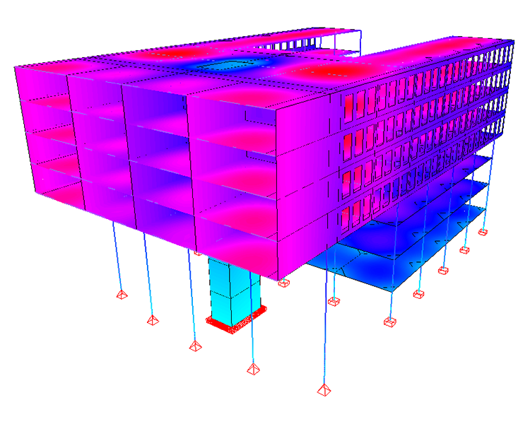
Concrete
Diamonds calculates the optimal reinforcement solution according to Eurocode and ACI. This serves as a starting point for a practical reinforcement definition. You can then calculate cracked deflections and crack widths for bar and plate elements or verify punching for plates and footings. For beams, complete reinforcement drawings can be generated with ConCrete Plus.
- Eurocode 2 (UK, DE, ES, PL, ...) and ACI
- Optimal reinforcement quantities
- Cracked deflection with creep
- Crack widths
- Deformation in time
- Punching verification
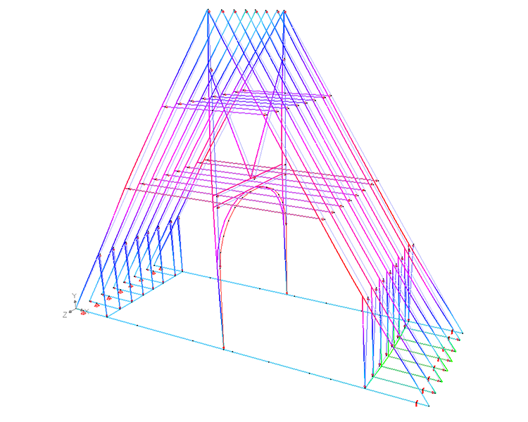
Timber
Diamonds calculates the deflection with creep effects, based on the service class. On execution the Eurocode timber verifications, buckling lengths and lateral torsional buckling supports are taken into account. These can be user-assigned or automatically calculated. Based on these unity check verifications Diamonds calculates the most optimal cross-sections.
- Eurocode 5 (BE, NL)
- Service class and load duration class
- Buckling length calculation
- Lateral torsional buckling supports
- Creep calculation
Fast and easy structural analysis with Diamonds
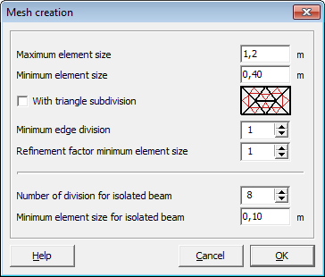
Input
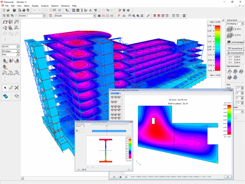
In spite of its power and completeness, Diamonds is easy to use thanks to its intuitive user interface. The graphic input does not only mean an enormous save of time, but you also lower the risk of making mistakes, thanks to the permanent visual control over the model. Your learning curve is short - guaranteed, in no time you are up and running with Diamonds. You will soon be assessing the impact of specific design changes on structural behaviour and use the available analysis results to optimize the economy of your designs.

Analysis
Diamonds’ analysis engine is based on the robust and powerful PARDISO sparse solver technology. Combining high speed performance with minimal memory usage, Diamonds will solve both simple 2D and complex 3D structural analysis models in no time.
Reporting
Thanks to the unique sub-reports concept, you can quickly compose a complete and well-structured custom report. Simply define the appropriate model orientation and visibility for each individual sub-report. Diamonds produces for you a table of contents based on the heading of one or multiple sub-reports. Reports can be printed out directly (with preview mode) or can be saved as an RTF file (Rich Text Format)

30-days testing all the possibilities, free of charge
Additional modules
Our modular product concept enables you to optimally fit our products to your application needs. You pay only for what you really need - and you leave open all options to upgrade in the future to a higher level of functionality, such as seismic or dynamic analysis, fire resistance analysis or moving loads.
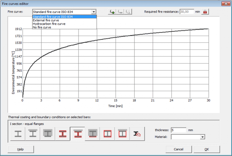
Fire resistance
As Diamonds includes an advanced thermodynamic solver, both solid and slender type of cross-sections can be analysed accurately.
- Fire curve and fire duration
- Predefined thermal protections available
- Thermodynamic calculation incl. radiation, convention & conduction
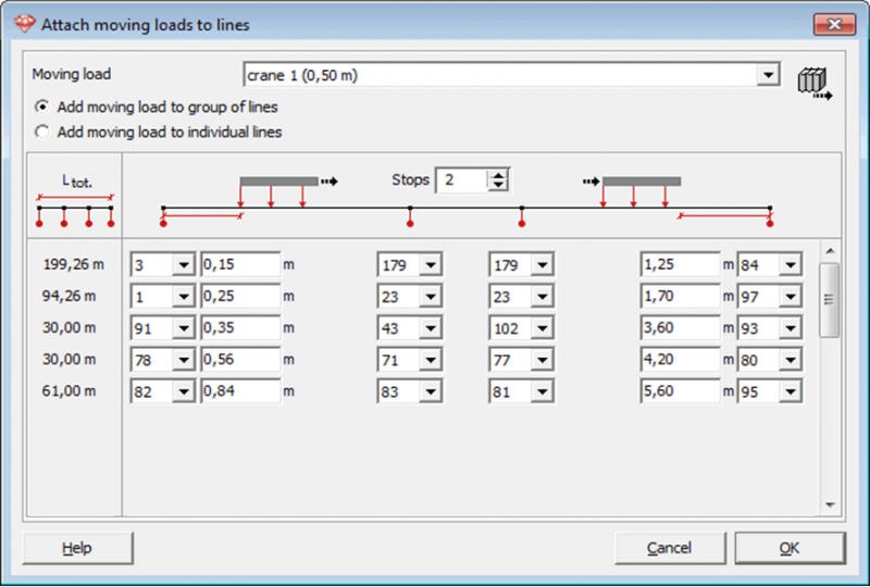
Crane loads and load trains
Diamonds calculates the structure for each position of the load train, straight or curved, and presents the results in the form of an envelope.
- Automatic detection of maximum path length
- Synchronization points for different trajectories
- Animated display of the progressive train load
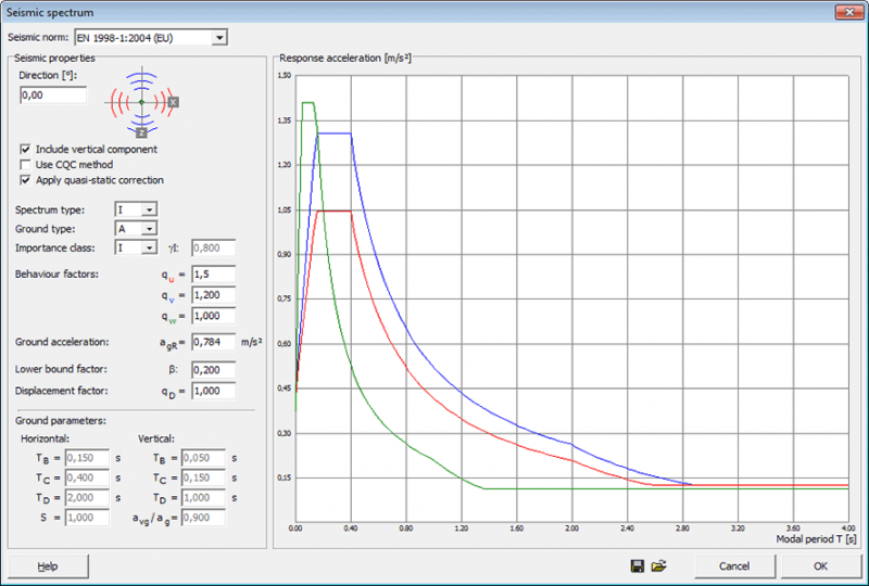
Seismics
With Diamonds you design structures requiring earthquake resistance, thanks to the effective modal masses summary for each direction
- Seismic design spectrum and seismic combination ULS SC
- Eurocode 8, NPR 9998 , ASCE 7-10 or user-defined
- Calculation of reinforcement, resistance & stability incl ULS SC
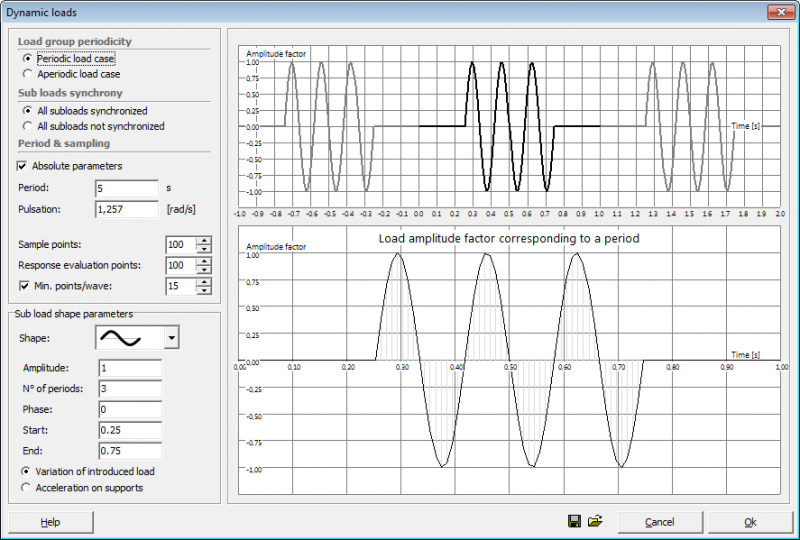
Dynamics
Diamonds’ multi-modal response analysis capabilities, allows dynamic variation of loads or acceleration of supports of all 3D structures.
- Periodic and aperiodic loads
- Harmonic, pulse, linear or user defined signal
- Dynamic response, eigenfrequencies and eigenmodes
Fast and easy structural analysis with Diamonds
Licenses and pricing
Subscription
- license limited in time
- pay per month or per year
- updates
- support
- Price: (from) 129€ per month
Purchase
- perpetual license
- one-time investment
- updates (if with maintenance contract)
- support (if with maintenance contract)
- Price: via quotation