

It all starts with the architectural model and schematizing
Schematizing is the process of simplifying a real building (the architectural model) into a structural analysis model, also called a wireframe model or mechanical model, that software can actually calculate. It means idealizing three things: the geometry (system lines and planes instead of real shapes), the supports (how the structure connects to the ground), and the joints (how structural parts connect to each other). Get these three idealizations wrong, and every downstream calculation inherits the error. Below, we walk through each one, then apply them to a real portal frame in Diamonds.
We will strip the architectural model until only the load-bearing structure remains. The load-bearing structure will transfer the applied loads to the ground. Possible loads that apply are the self-weight of the structure and weight resulting from the use of the structure (people, furniture, machines). Wind, snow, temperature changes, etc. can also cause loads, so they must be considered.
To make the load-bearing structure accessible for calculations, we must schematize it to an analysis model (syn. wireframe model, mechanical model). This goes hand in hand with necessary idealizations and simplifications The idealizations are in the areas of:
- The geometry (the shape and dimensions) of the structure
- The supports
- The joints
Shape of the structure
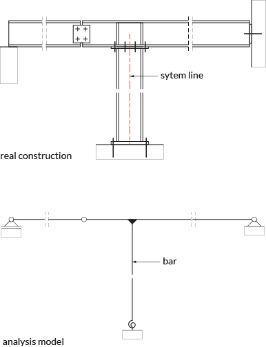
Through schematization, system lines that coincide with the axis lines of the cross-sections will replace beams and columns. Similarly, system planes that coincide with the axis plane will replace floors and walls.

Because we are working with system lines and planes, the calculated value of the spans in an analysis model is slightly different from the actual dimensions that we find in the real construction (=architectural model). In Figure 3:
- the bars in the analysis model are slightly shorter than in reality
- the columns are a little longer than in reality
When the position of the system lines and planes is determined, we must assign a cross-section to them. The better this initial choice is in line with the final design, the less calculation work. As a guide, we can estimate the initial cross-section of each element using the rules of thumb in the table below.

| Floor beams | ||
|---|---|---|
| Concrete | In-situ |
L/10 (single field) |
| Prestressed | L/20 | |
| Steel | L/15 to L/20 | |
| Timber | Sawn | L/20 |
| Laminated | L/17 | |
| Roof beams | ||
| Concrete | In-situ | L/20 |
| Prestressed | L/20 | |
| Steel | L/30 | |
| Timber | Sawn | L/20 |
| Laminated | L/12 | |
| Columns | ||
| Concrete | 1-storey (L<=8m) | L/12 to L/15 |
| Multiple storeys (L <= 4m) | L/10 to L/12 | |
| Steel | 1 storey (3m <= L<= 8m) | L/20 to L/25 |
| Multiple storeys (3m <= L<= 4m) | L/7 to L/8 | |
| Timber | 1-storey | L/20 |
| Concrete floors | ||
| Line supports (up to 7m) | Single field |
L/22 |
| Continuous | L/30 | |
| Point supports (up to 7m) | L/25 to L/28 | |
| Coffered floor, hollow floor, ribbed floor (up to 20m) | 1/20 to 1/25 x diagonal length | |
| Hollow-core slabs (up to 17m) | L/35 | |
| Double tee flooring (up to 22m) | L/30 | |
Supports and joints
A (part of a) construction does not float freely in the air. Structural parts are interconnected in joints (syn. nodes). And the structure is connected to this planet through supports that divert the internal forces to the ground.
The schematizing of supports/nodes depends on their possible degrees of freedom. These degrees of freedom play out at two levels:
- On the one hand, the translational stiffness measures the resistance of the support/joint to displacements.
- On the other hand, the rotational stiffness measures the resistance of the support/joint to rotation.
A support/joint always limits at least one degree of freedom. In a two-dimensional[1] flat plane, a support/joint has a maximum of 3 degrees of freedom: two translational and one rotational (Figure 4).

By playing around with the translational and rotational stiffness, we can distinguish different supports/joints (Figure 5).
- Hinged, rolled, and restrained are the most used supports. Both the translational and rotational stiffness are important here.
- To classify joints, usually only rotational stiffness is used.
- Joints with a free rotation are called hinged joints.
- Joints in which rotation is prevented are called rigid, fixed, or continuous joints.
- Joints with limited rotational stiffness are called semi-rigid joints.
| ROTATIONAL STIFFNESS | |||||
| Free | Limited | Fixed | |||
| JOINTS |  Hinged node |  Semi-rigid node |  Rigid node | ||
| SUPPORTS | TRANSLATIONAL STIFFNESS ↔ | FREE |  Roller support |  |  |
| IMPEDED |  Pinned support | Semi-fixed |  Built-in | ||
| TRANSLATIONAL STIFFNESS ↕ | Usually prevented, but LIMITED can be created by applying a spring in the vertical direction. | ||||
When making a structural analysis model, we must therefore schematize the supports and joints so that they approximate the real behaviour as closely as possible. In Figure 6, you can see the same construction as in Figure 1, but this time the supports and joints are shown together with their respective schematization. For example, the left support from the architectural model is translated into a roller support in the analysis model. Or the flexible column base plate connection to semi-rigid support, and so on.

The table below show pictures of actual supports/joints and their associated schematics.
| Examples of supports | Examples of joints | ||
|---|---|---|---|
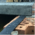 | A neoprene strip is placed between a pre-slab and a load-bearing wall. The neoprene strip ensures that the pre-slab can undergo small horizontal movements. | 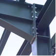 | Classic bolted beam-column connection with a haunch. The haunch provides extra rotational stiffness. |
 | Schematization: roller support |  | Schematization: rigid node |
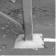 | Both translational and rotational displacements are prevented in this support. | 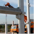 | Beam-column connection in concrete where a console supports the beam. Usually, this joint cannot transfer moments. |
 | Schematization: built-in |  | Schematization: hinged node |
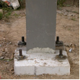 | The four bolts ensure that this support can develop a specific moment resistance. Unfortunately, this resistance is not of the same magnitude as a built-in support. | 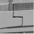 | A beam-beam connection in concrete. Also called a corbel. This joint cannot transfer moments. |
 | Schematization: semi-fixed support |  | Schematization: hinged node |
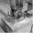 | Only in bridges, you can encounter supports in their purest form. This example is a pinned support. The displacements are prevented, but the bar connected to the support can rotate uninterrupted. | 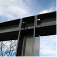 | A bolted beam-column-beam connection without haunches. This connection has a specific rotational stiffness but not the same magnitude as if haunches were present. |
 | Schematization: pinned support | 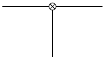 | Schematization: semi-rigid node |
If a certain degree of freedom (translational or rotational) is free or fixed, the structural analysis model of the support/joint is quickly determined. It’s all or nothing. But with translational springs and rotational springs, it’s a different story. There are several ways to determine the value of those translational and rotational springs within structural analysis. However, it is beyond the scope of the article.
Practical application: structural analysis model in Diamonds
Let us apply the knowledge in Diamonds, our core structural analysis software. We create the structural analysis model for the second frame in the hall below.

The dimensions of the system axes are as follows:
- Width: 12m
- Column height: 6m
- Roof slope: 15°
To better understand where the system axes are exactly, we draw them on the picture:

Next, we must assign sections to the system axes. Based on Table 1, we can make a first estimate:
- Columns: 6000 mm / 20 = 300 mm > HEA 300
- Beams: 6000mm/ 20 = 300mm > IPE 300
- Haunches: length 1m, height equal to the IPE height at which the haunch is attached
- Supports: assume hinged
- Joints: fixed joints (due to the presence of the haunch). Joints are fixed by default in Diamonds.
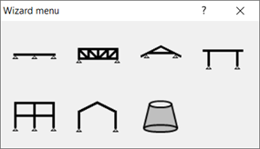
To quickly generate a portal frame, we use the structure wizard.
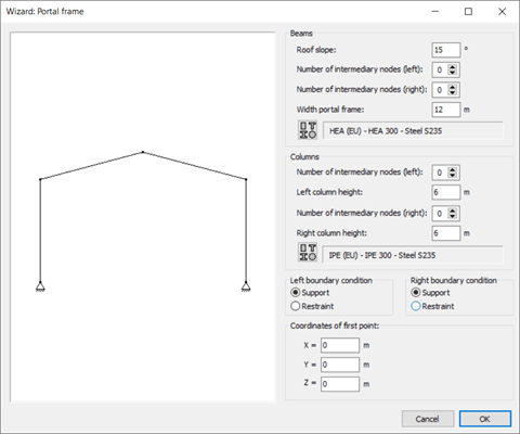
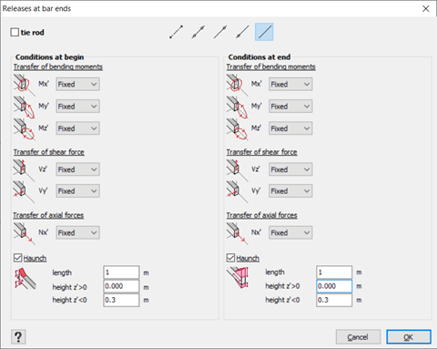
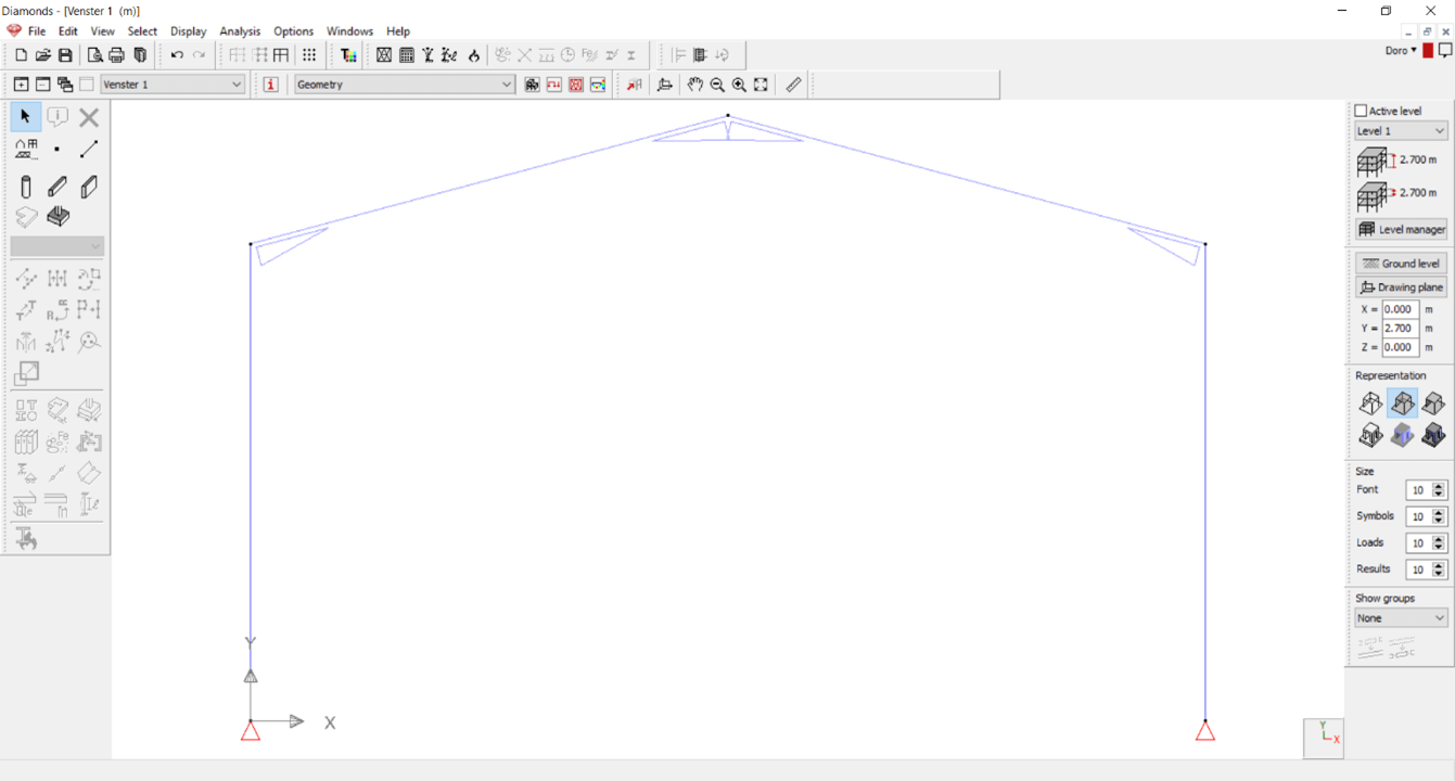
The portal frame is shown in a wire representation in the image above: only the system lines are visible. If you request a solid representation, the section dimensions are generated and pasted onto the system lines. As a result, this representation does not look like the real construction (= architectural model):
- Beams and columns don’t seem to line up nicely.
- The beam-beam joint in the ridge also doesn’t seem to connect well.
- The haunches overlap in the ridge (this can even be seen in the wireframe).
But these things are normal. They result from schematizing an architectural model (which is not suitable for calculations) to a structural analysis model (which is suitable for calculations).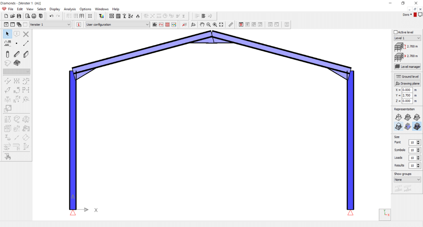
Literature:
- Braam, R., & Lagendijk, P. (2010). Constructieleer gewapend beton (7de editie). Vrije Uitgevers, de.
- Stark, J., & Wardenier, J. (2014). Knopen (1ste editie). Bouwen Met Staal.
- Dicke, D. (1991). Stabiliteit voor ontwerpers (2e druk). Delftse U.M.
- Vuistregels voor het ontwerpen van een draagconstructie. (2013, 20 november). Wiki BK TU Delft. Geraadpleegd op 19 januari 2021, van http://wiki.bk.tudelft.nl/mw_bk-wiki/images/1/12/Vuistregels.pdf
- Hanaor, A. (1998). Principles of Structures. Blackwell Publishing.
FAQ
What is schematization in structural analysis?
Schematization is the process of simplifying an architectural model, what a building actually looks like, into a structural analysis model that software can calculate: replacing beams and columns with system lines, and floors and walls with system planes, then assigning supports and joints that approximate real behaviour.
What’s the difference between a support and a boundary condition in a structural model?
A support connects the structure to the ground and diverts internal forces into it. A boundary condition happens in a node, connecting two structural parts to each other. Both are classified the same way, by their translational and rotational stiffness, ranging from fully free (hinged) to fully fixed (rigid), with semi-rigid options in between.
Why does the schematized model look slightly different from the real structure?
Because system lines and planes run through the axis of each cross-section, not its edges, calculated spans in the analysis model are slightly shorter for beams and slightly longer for columns than the real dimensions. This is expected and doesn’t indicate an error.
Next step
Want to see schematization applied to your own structure? Try Diamonds free for 30 days, fully functional, no obligation.


